
Low-Carbon Adaptive Reuse
Climate Resilience and Energy Retrofit for Alley-Eblana Brewery
Team MChi Zhang, Ines Bici, Joe Russell, Peihao Jin, SpurtyKamath, Tony Lau, Veronika Ikonnikova
A 19th‑century brewery complex in Mission Hill becomes a testbed for flood‑resilient, low‑embodied‑carbon adaptation in a rapidly warming Boston, developed as a group provocation for SCI 6502: Advanced Reverse Design and Embodied Carbon at Harvard GSD. The project couples a careful structural retrofit—prioritizing retention of the existing brick-and-iron shell and targeting high‑impact elements like slabs and cores—with an integrated landscape hydrology strategy of terraced bioswales, permeable surfaces, biodrainage planting, and site‑wide rainwater harvesting. Over a 50–100‑year horizon, the derelict industrial structure is reimagined as a resourceful community hub where long life, adaptable program, and visible water stewardship operate as a model of responsible design under climate change.
Site Context & History
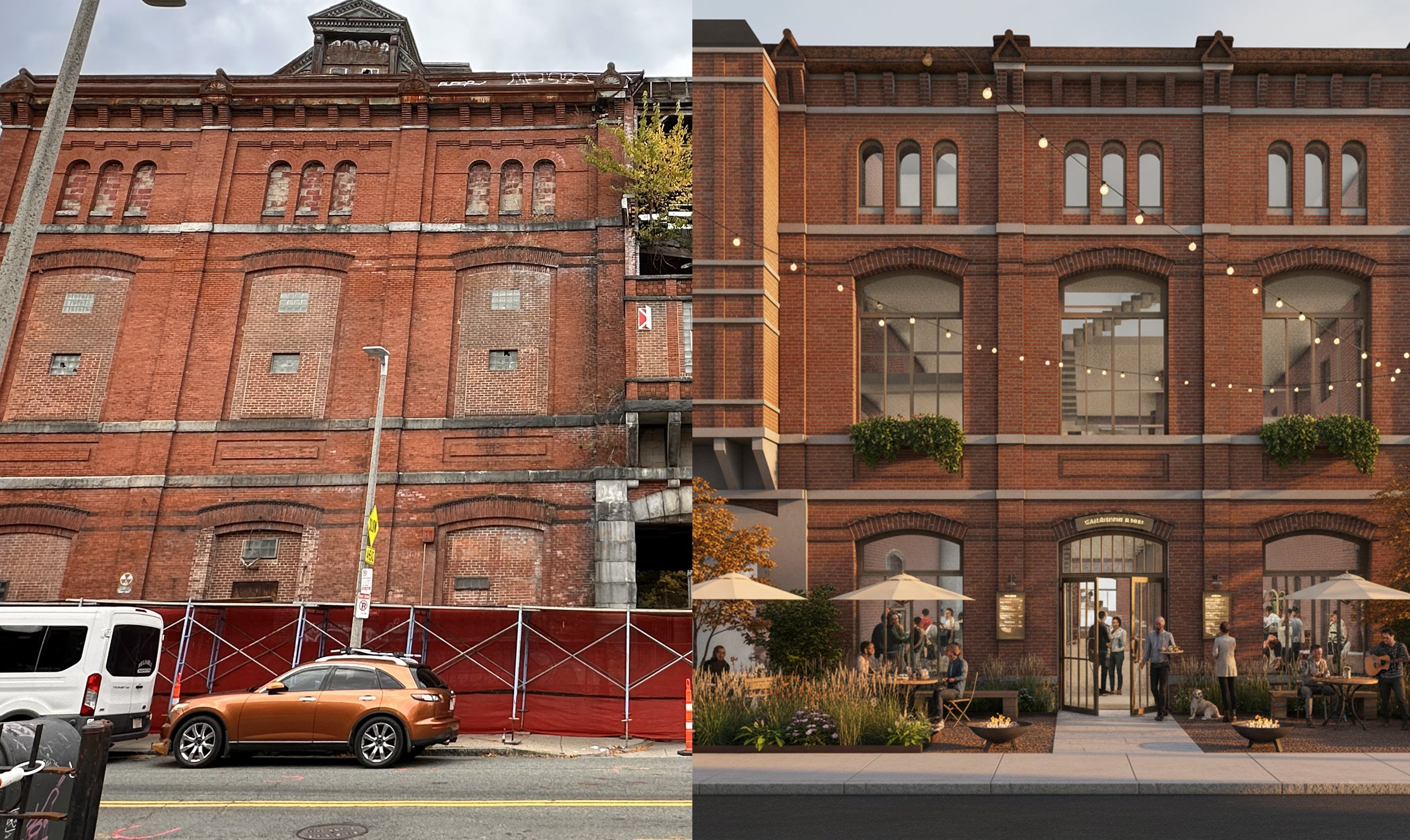
The Alley‑Eblana Brewery sits on a steep slope in Boston’s Mission Hill neighborhood, within the historic Stony Brook breweries corridor where topography and water infrastructure originally supported gravity‑driven brewing industries. Over time, the complex cycled through multiple industrial uses—from brewing to warehousing, medical manufacturing, and auto repair—before being largely abandoned and repeatedly threatened with demolition for luxury housing. The project situates itself against this background of extraction and speculation, arguing for a different future in which the building’s industrial heritage, hydrological setting, and community context are treated as assets rather than liabilities.
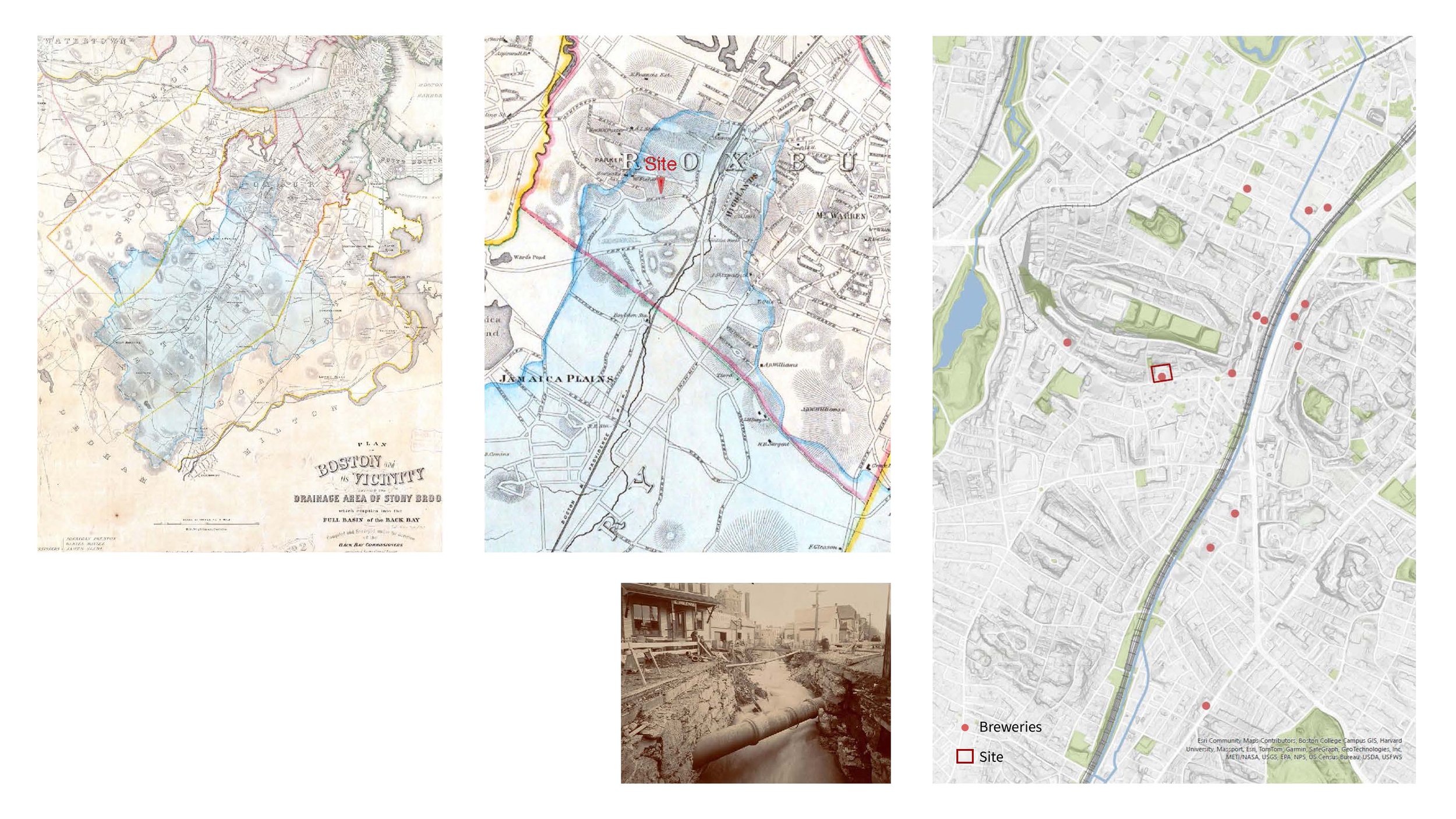
Stony Brook was once a surface waterway through Roxbury and Jamaica Plain that made the valley ideal for water- and steam-powered industry, leading breweries to cluster there for gravity drainage, water supply, and rail access, an area now known as the Stony Brook Breweries District.
New Programming
The proposal repositions the former brewery as a resourceful community hub instead of a closed industrial plant. Ground‑level spaces and the landscape host public‑facing uses such as events, shared workspaces, and small‑scale production, while upper floors accommodate flexible studios and light fabrication. This mixed‑use programming is designed to serve nearby residents, students, and healthcare workers, making climate infrastructure visible and legible as part of everyday life rather than an invisible technical layer.
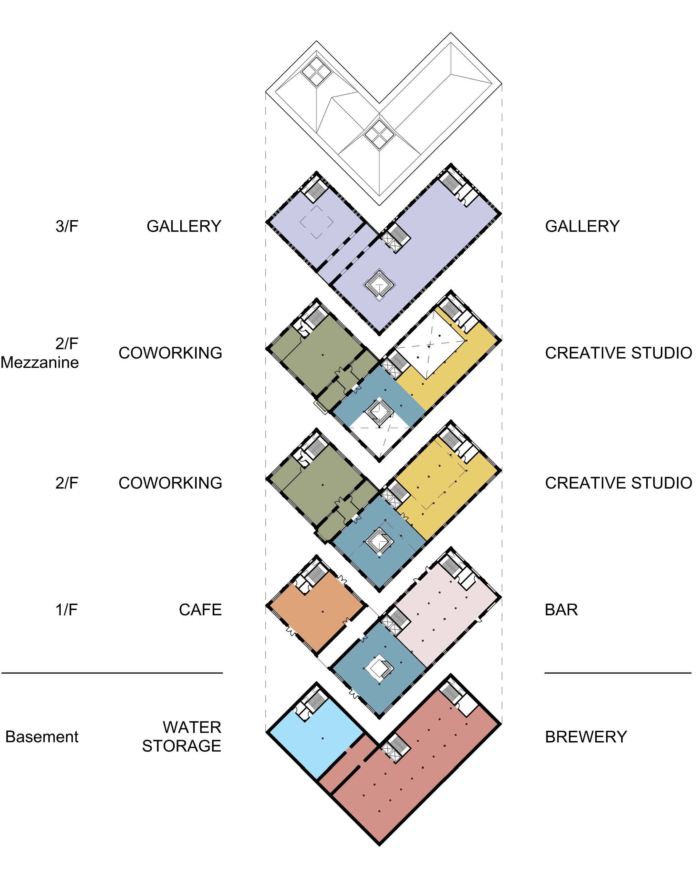
Isometric Retrofit
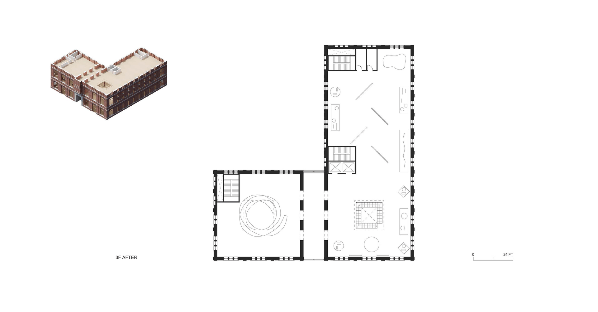
Third Floor
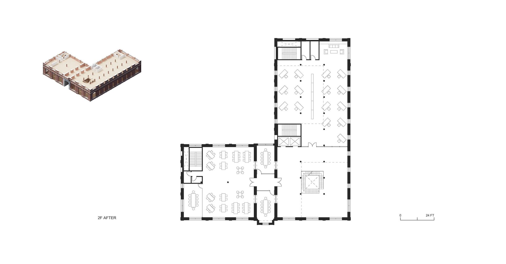
Second Floor
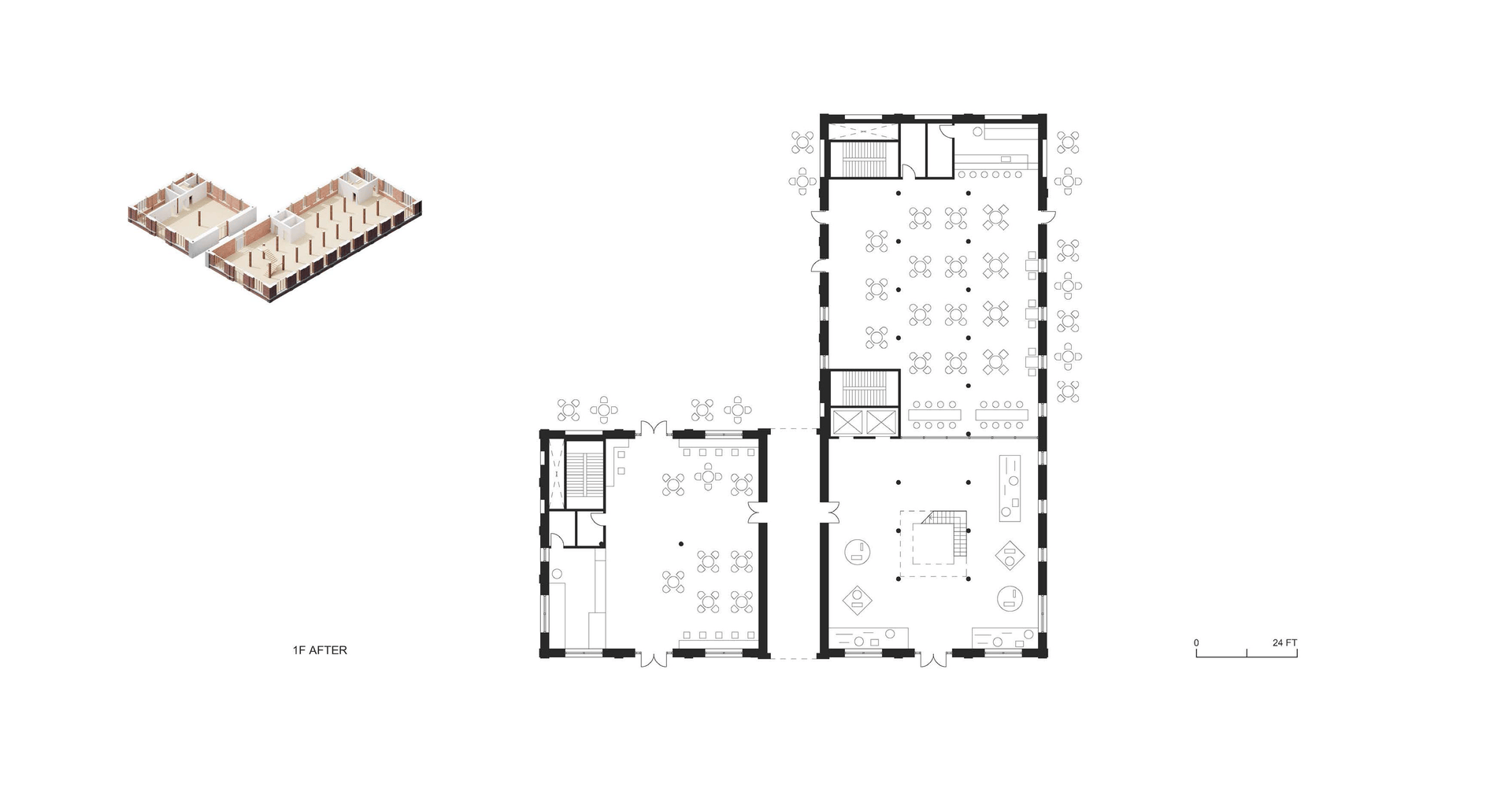
First Floor
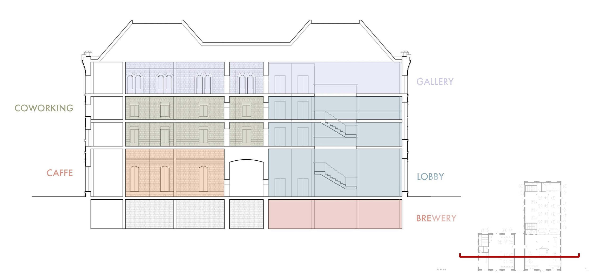
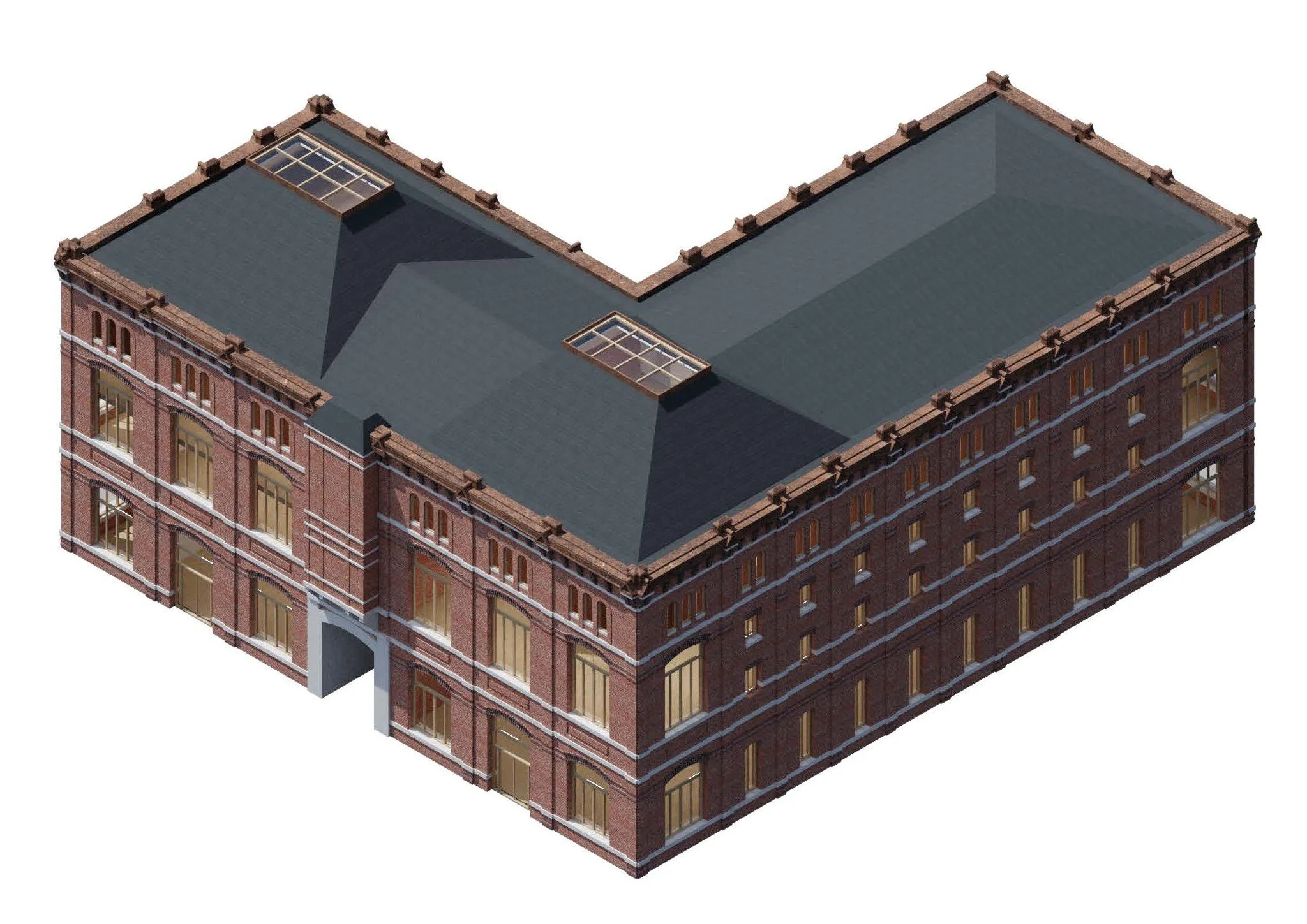
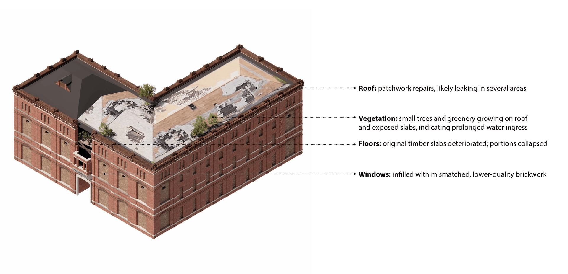
Retrofitting Strategy
The retrofit approach follows a “retain, repair, insert” logic. The existing brick envelope and cast‑iron structure are stabilized and restored, including reopening original window bays and removing incompatible infill where possible. Within this repaired shell, new floor systems, stair and elevator cores, and a hybrid roof structure are inserted to meet contemporary performance requirements while keeping new structural additions as targeted and efficient as possible.
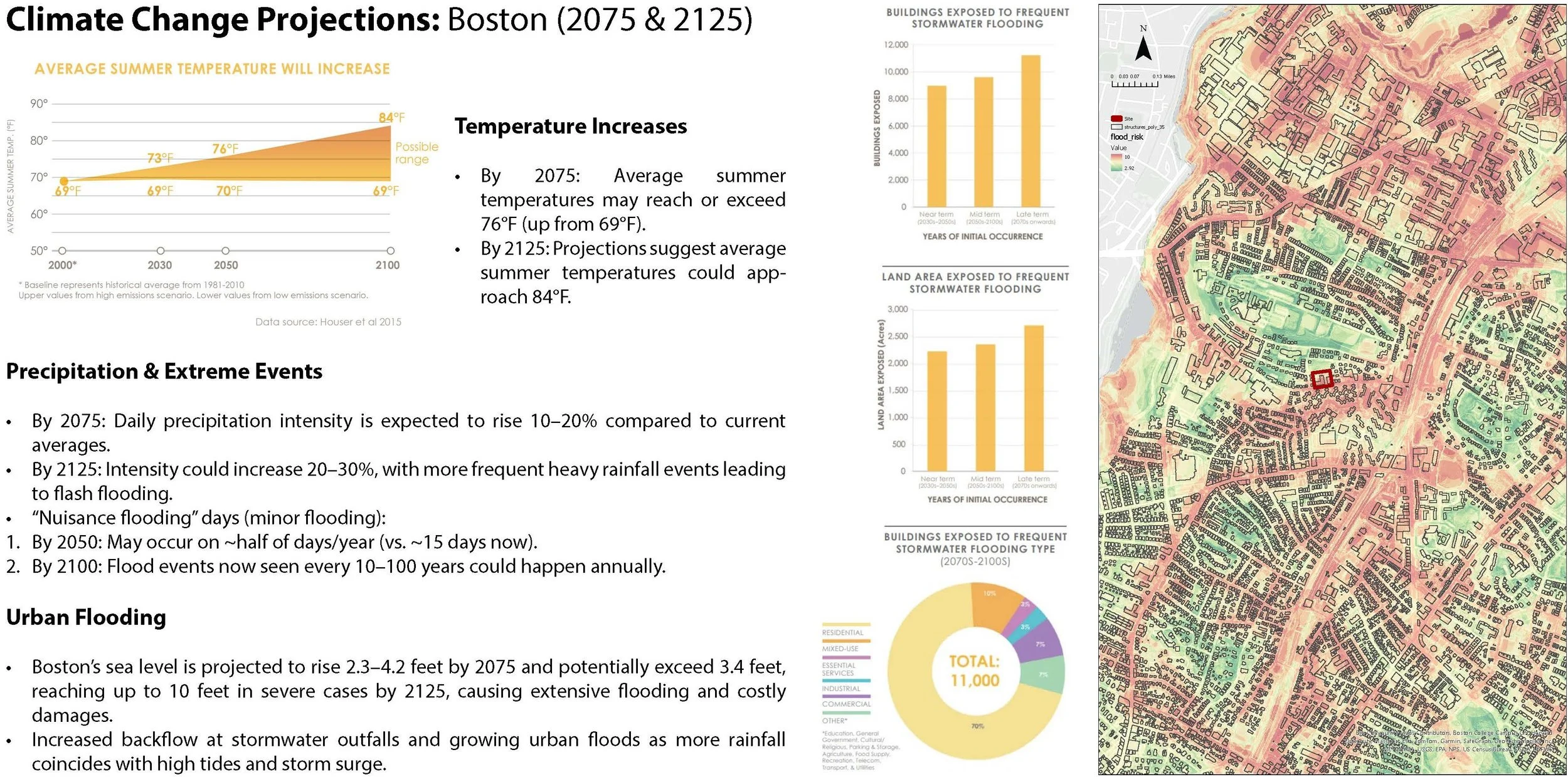
Climate Adaptation
The design looks toward mid‑ to late‑century conditions in Boston, with hotter summers, more intense rainfall events, and more frequent urban flooding. Rather than treating these shifts as external constraints, the project uses them as primary form‑giving forces for both architecture and landscape. Climate adaptation becomes the organizing premise: the way water moves, accumulates, and is reused on site drives how outdoor spaces are shaped, where structure is reinforced, and how the building can remain viable over a 50–100‑year horizon.
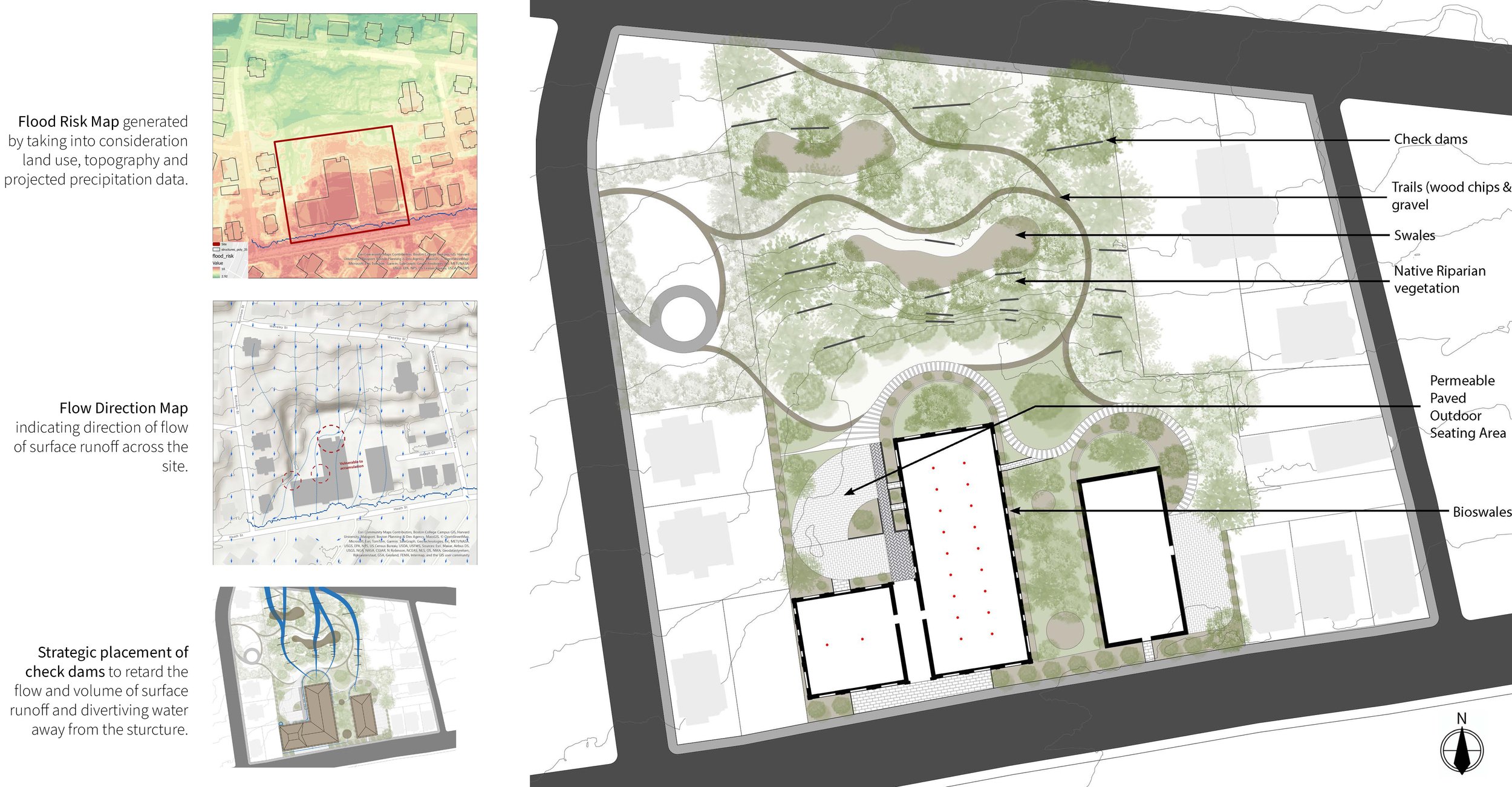
Flood Resilience & Landscape Strategies
Initial analysis revealed that the brewery’s steep north slope funnels runoff toward the building, while a low corridor along the southern edge acts as a collection path, creating high flood vulnerability. The landscape strategy transforms this liability into a hydrological device by stepping the grade into terraced bioswales held by check dams, which slow water, promote infiltration, and reduce erosive velocities. At the base of the slope, deep tap‑rooted native trees function as biodrainage, increasing evapotranspiration and allowing higher absorption without oversaturating the water table.
Across the site, permeable surfaces and planting further reduce runoff and treat water as a resource. Salvaged bricks from window infill are reused as permeable paving over an engineered aggregate base, turning demolition waste into flood‑mitigating ground. A network of rain gardens and bioswales around the building collects residual runoff and routes it either into on‑site storage or into recharge pits, improving groundwater recharge and reducing pressure on municipal storm infrastructure.

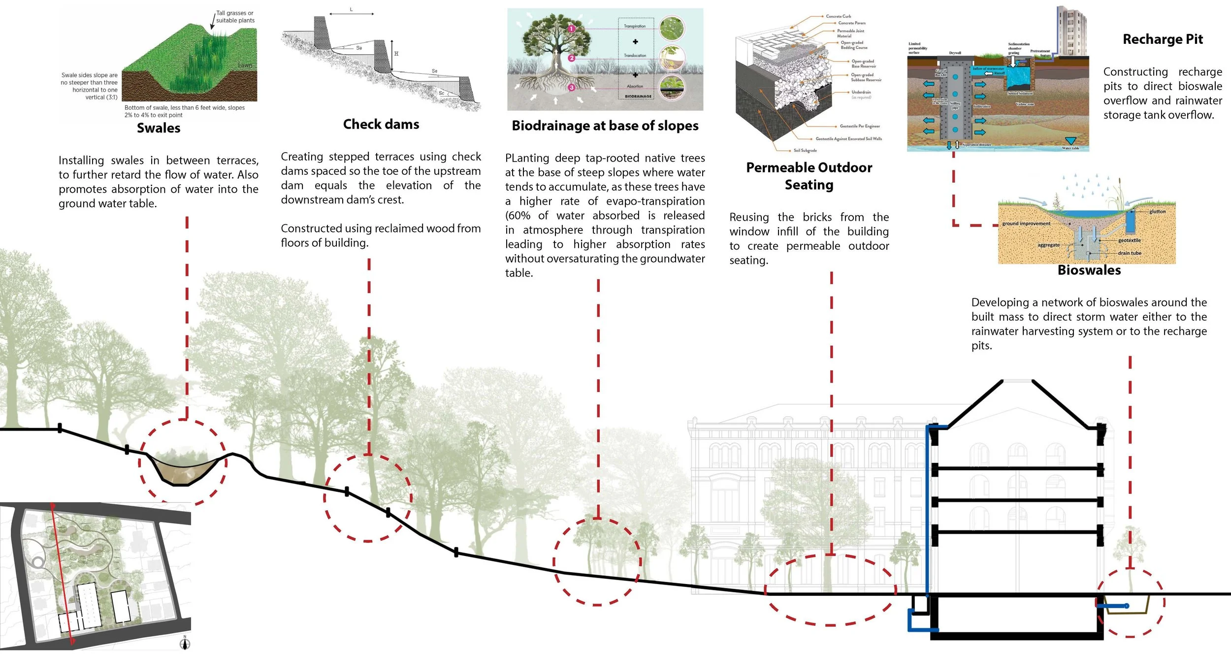
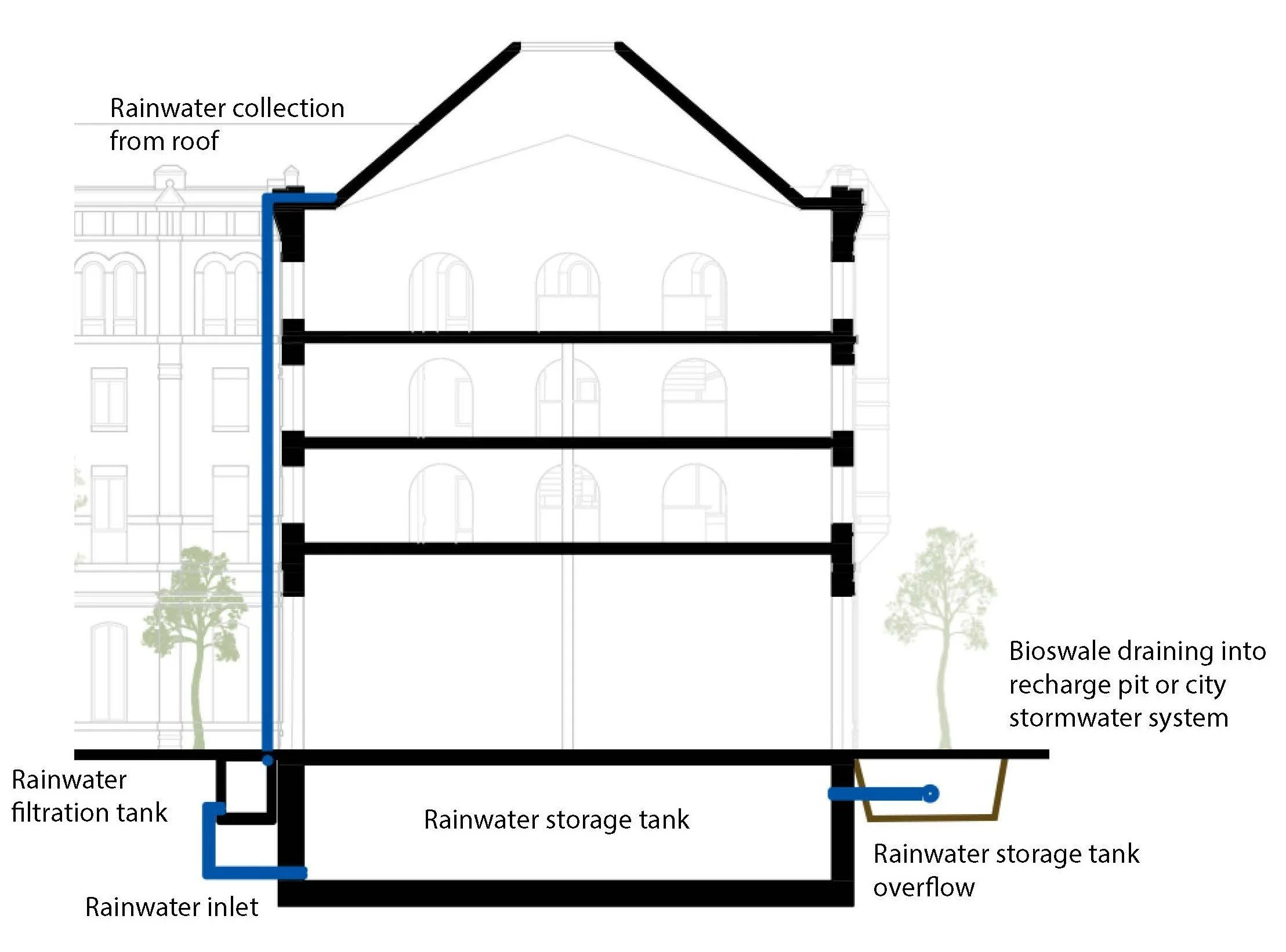
Rainwater that falls on the building itself is captured at the roof and routed through the bioswale network into a basement storage tank, sized to serve the building's non‑potable water demands. Rather than a single isolated tank, the system extends collection across the entire site — roofs, permeable courtyard, and hardscape — turning the whole property into a catchment. When storage capacity is exceeded during heavy rainfall events, controlled overflow is directed through secondary bioswales to subsurface recharge pits, replenishing local groundwater rather than burdening the municipal stormwater network. This transforms what was a critical flood liability into a closed-loop resource system, and gives the building a second life as infrastructure for the landscape around it.
Embodied Carbon & Material Strategy
Because new floor slabs and vertical cores account for the majority of new material volume, the embodied‑carbon strategy focuses on these elements. The project compares mass‑timber and concrete solutions, recognizing that while CLT can perform well in conventional carbon accounting, hidden impacts from forestry practices, transport, manufacturing waste, and adhesives complicate its footprint. The preferred path employs optimized low‑carbon concrete mixes with high supplementary cementitious content and locally produced net‑zero cement, reducing both process emissions and transport‑related impacts. Throughout, the structural system is geometrically and materially optimized to do more with less, aligning the retrofit with long‑term performance and carbon‑reduction goals rather than treating structure as a neutral backdrop.